










1. Introduction: Why Does “Inversion” Happen? Inversion Is Not a Sensor Failure—It’s a Misalignment of Conventions
In industrial automation, determinations such as “object present/not present” and “in position/not in position” are typically implemented using discrete (switching) sensor outputs and connected to the PLC’s digital inputs (DI). When the system shows “inversion,” the essence is that the sensor side has already produced the correct output according to the physical state, but the PLC side reads the logic (valid/invalid) opposite to the engineering expectation—so the interlocks and action sequences are triggered incorrectly.
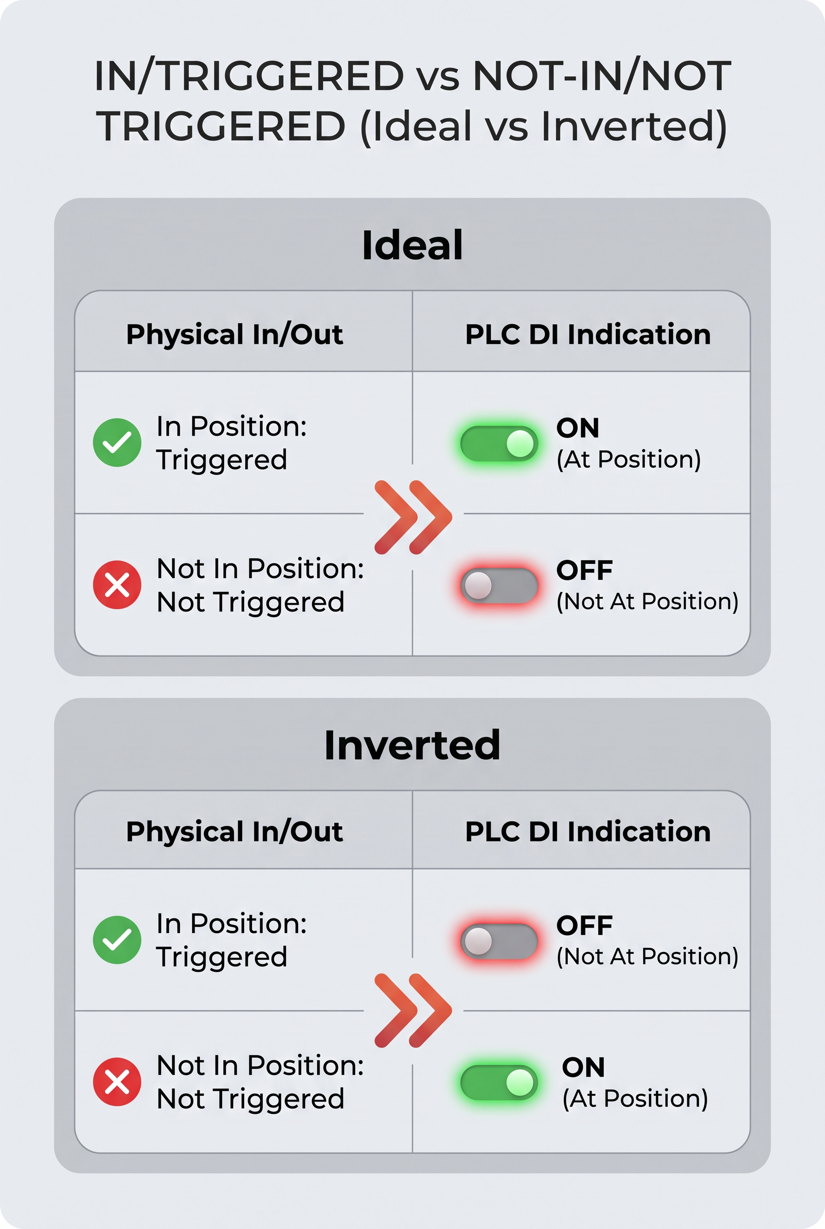
This kind of “inversion” often does not come from sensor detection failure; it comes from a mismatch between the output logic definitions and the PLC input logic definitions. Discrete outputs include at least two layers of meaning:
• NPN/PNP: These are two different output modes (output polarity/drive mode). They determine what kind of conduction state and level logic the PLC DI terminal ultimately presents.
• NO/NC: These are normally open / normally closed contact logic rules. They determine whether the contact is open or closed when not triggered vs. triggered.
For ultrasonic sensors (for example, the ISUB100 series), detection itself may be working correctly; however, if the PLC-side reading convention is reversed, it will create a fault that looks like inversion.
The core engineering approach is: make the output logic a verifiable mapping relationship—confirm NPN/PNP, NO/NC, and match them to the PLC DI common terminal type.
2. First, Separate Two Things Clearly: What NPN/PNP Determines vs. What NO/NC Determines
When integrating a discrete sensor into a PLC DI, be sure to break down the “output definition” into two layers and understand them separately:
• NPN/PNP solves how the electrical side sends the signal to the PLC.
• NO/NC solves what contact state the output presents on the logic side when not triggered vs. triggered.
As long as one layer is inconsistent with the PLC input method or the engineering expectation, inversion can occur.
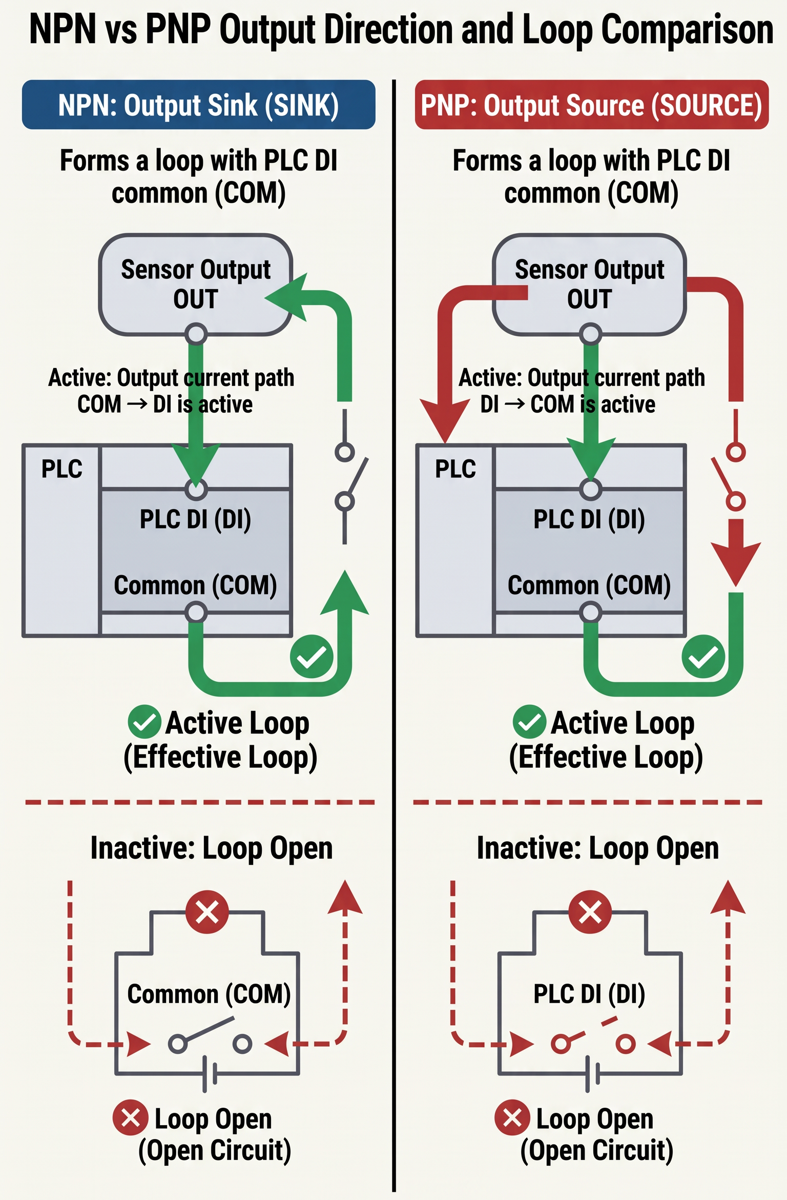
2.1 NPN/PNP: Determines “How the Output Works With the PLC DI Common Terminal”
NPN/PNP are two different output modes (output polarity/drive mode). They determine, during operation, what the relationship is between the sensor’s output current (or conduction path) and the PLC input common terminal—thereby affecting which final state the PLC DI terminal sees (typically expressed in engineering as a valid/invalid level corresponding to the common terminal type). Therefore, to judge whether inversion will occur, the first step is not to check whether the output indicator lamp is on. Instead, match the sensor output type with the PLC DI terminal’s common terminal mechanism. During integration, you must confirm—based on the PLC digital input configuration—whether the output should be set to NPN or PNP to ensure the output signal is compatible with the input common terminal / valid level.
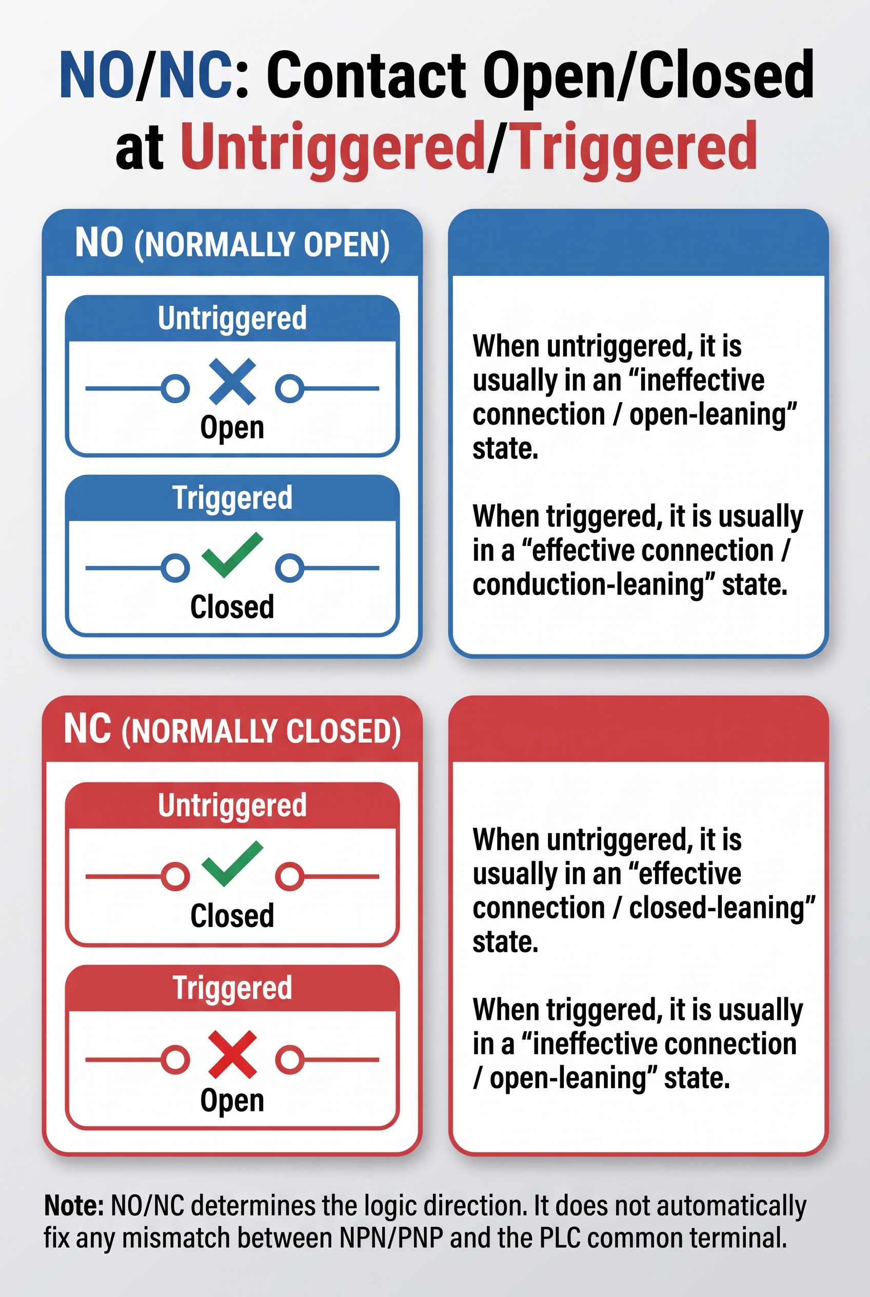
2.2 NO/NC: Determines the Contact Logic in the “Not Triggered / Triggered” States
The meaning of NO/NC is normally open / normally closed (standard contact logic). It defines the connection relationship that the output terminal should present in two states—not triggered (object not present / not in position) and triggered (object present / in position)—thereby affecting the PLC-side “valid definition.”
An intuitive way to understand it is:
• NO (Normally Open): when not triggered, it is typically in an invalid connection / open tendency; after triggered, it shifts to an valid connection / conducting tendency.
• NC (Normally Closed): when not triggered, it is typically in an valid connection / closed tendency; after triggered, it shifts to an invalid connection / open tendency.
It is important to note that NO/NC determines the logical direction (whether it should become “valid” or “invalid” when triggered). It does not automatically correct the mismatch between NPN/PNP and the common terminal; the two must be matched together.
Key to avoiding inversion: it is not just about selecting the correct NPN/PNP or the correct NO/NC. Instead, you must match NPN/PNP (electrical polarity / how it pairs with the common terminal) together with NO/NC (trigger logic direction), and align them with the PLC DI common terminal type and the valid level definition.
3. Use a “Logic Mapping Table” to Establish the Relationship
To avoid “the wiring is correct but the logic is reversed,” the most effective engineering method is to convert the sensor output definitions (NPN/PNP + NO/NC) together with the PLC DI input common terminal type (common positive / common negative) into the same judgment convention—meaning:when the object is in position / triggered and when the object is not in position / not triggered, the PLC DI should be read in the program as a high level (valid = 1) or a low level (invalid = 0).
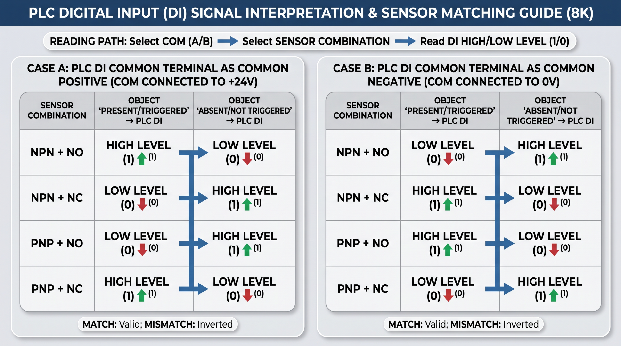
The table above is based on a common operating mode for 24V discrete DI: when the sensor output matches the PLC DI common terminal type, the sensor output being conducting corresponds to the DI being valid. If it does not match, the DI validity will be logically inverted.Different PLC input modules may differ slightly in their display method / valid definition, but the selection basis for the mapping relationship still follows the same logic. Ultimately, please confirm using the “field validation” in Section 5.
3.1 How to Use This Table to Identify the Cause of the “Inversion”
• First, confirm whether the PLC DI is in Case A or Case B: check whether COM connects to common positive (+24V) or common negative (0V).
• Then determine the sensor output combination: NPN/PNP + NO/NC.
• Match the input value (1 or 0) that the table indicates should be read for in position / triggered. If it is opposite to the field behavior, it usually means that at least one definition is not aligned—most commonly:
o NPN/PNP does not match the DI common terminal type;
o the NO/NC selection is opposite to the expected trigger logic (for example, you want in position = valid = 1, but you actually selected NC, which results in inversion).
4. PLC Wiring and Input Common Terminal: Where Inversion Usually Happens
“Inversion” does not come from a single independent parameter; it usually occurs during the stage where signal definitions are cross-translated: when the PLC-side input common terminal convention does not match the sensor-side output effective current flow direction / polarity convention, or when the contact (NO/NC) selection is opposite to the definition of what “triggered = valid” means. Especially when connecting a 3/4-wire sensor to PLC DI, the input common (COM) type is the key point for determining whether a point will be naturally inverted.
In addition, the following engineering changes also often cause inversion to appear or be “triggered,” for example: replacing the PLC input module (different modules have different valid definitions / display methods), replacing isolated/expansion I/O, or during maintenance, changing only the wiring without synchronously confirming that the sensor version (NPN/PNP, NO/NC) and the PLC DI common terminal settings remain consistent.
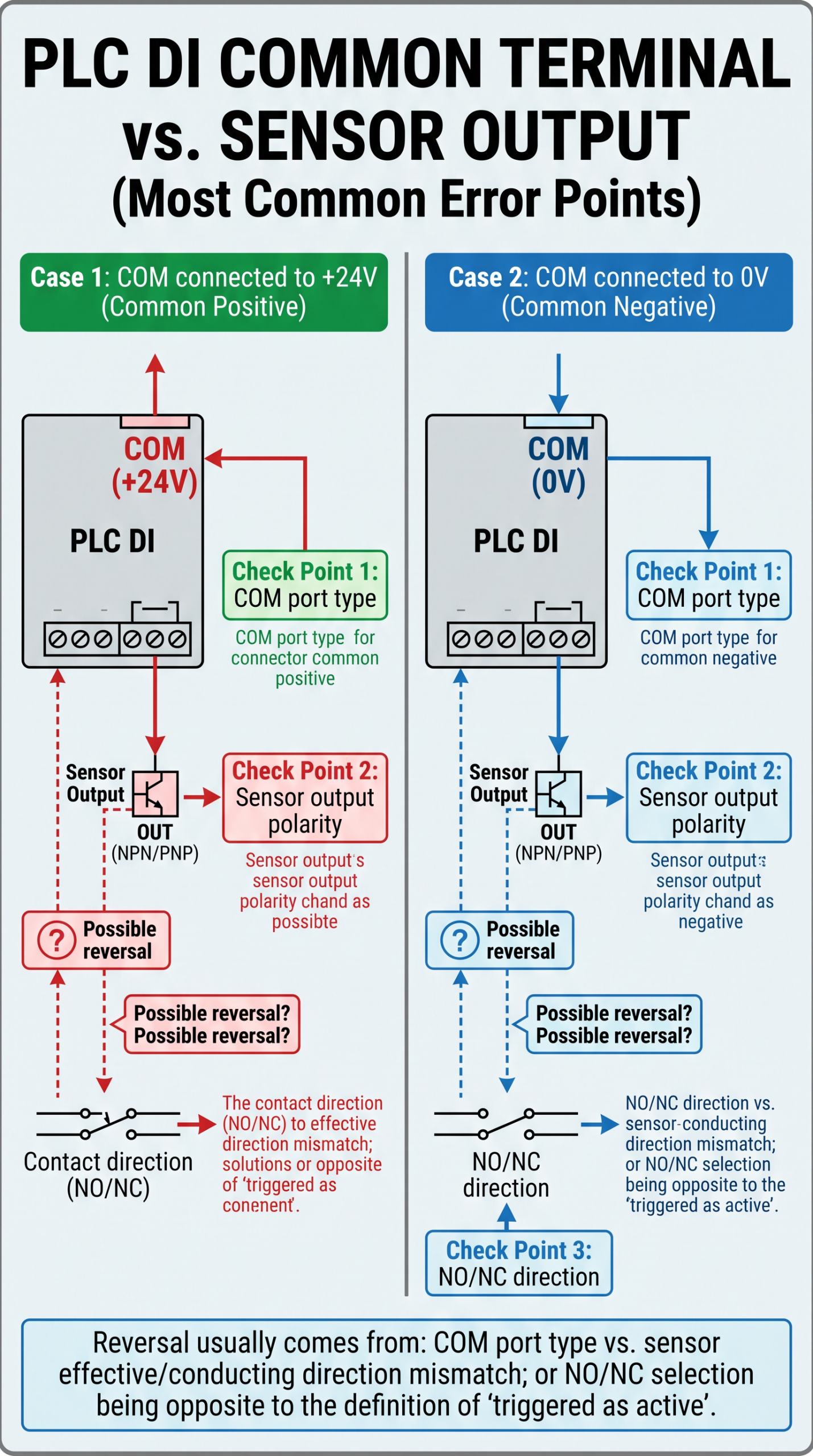
The main check point for inversion: PLC DI common terminal type • Common positive (COM connected to +24V): when the external load circuit is established in the way of “valid = conducting”, the PLC DI will typically identify it as high level valid (1). • Common negative (COM connected to 0V): when the external circuit is established, the mapping of “valid” for the PLC DI will change with the common terminal port convention, and ultimately shows on the program side as which side of the high level/low level is read.
5. Validation and Troubleshooting Workflow
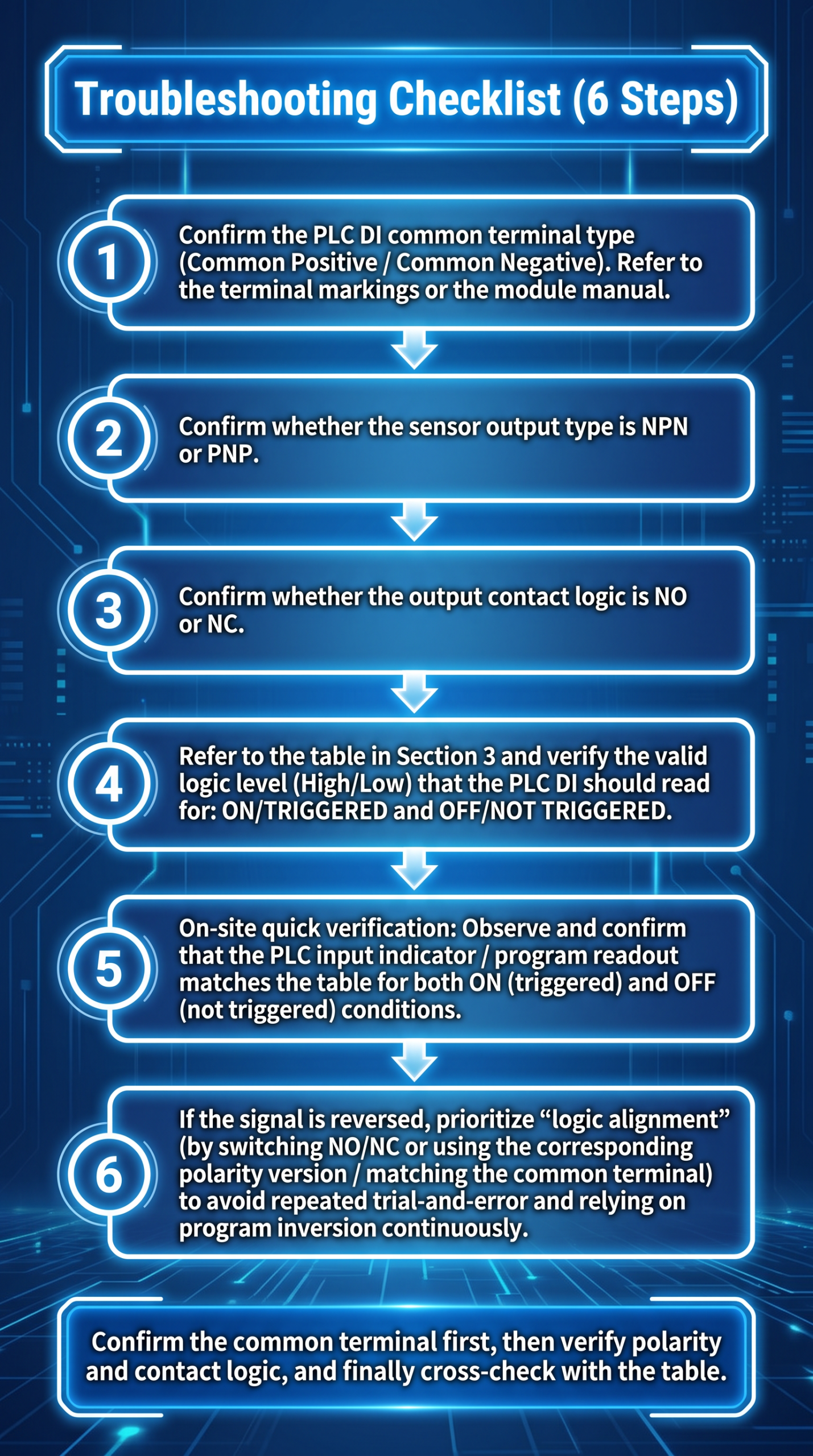
It is recommended to turn troubleshooting into a reusable step checklist to reduce repeated trial-and-error wiring: 1.Confirm the PLC DI common terminal type (common positive / common negative). Follow terminal labeling or the module manual. 2.Confirm whether the sensor output version is NPN or PNP. 3.Confirm whether the output contact logic is NO or NC. 4.Refer to the mapping table in Section 3 and verify the valid level (high/low) that should be read for PLC DI in the states in/triggered and not in/not triggered. 5.Field quick verification: observe whether the PLC input indicator / program read value matches the table in both in-position and not-in-position conditions. 6.If inversion is found, first adjust “logic alignment” (by switching NO/NC or replacing the corresponding polarity version / common terminal matching) to avoid repeated trial wiring and continuous reliance on PLC program inversion.
6. Conclusion: The shortest rule to avoid inversion
To completely eliminate “the wiring is correct but the logic is reversed,” the shortest path in engineering is not memorizing one parameter, but aligning all three into a single convention: “NPN/PNP + NO/NC + PLC DI common terminal type.” Once these three items match simultaneously, the “valid” level that the PLC reads on the input side will remain consistent with the field definition of “in position / triggered — not in position / not triggered,” thereby removing at the root the debugging cost and on-site risk caused by inversion.
PREGUNTAS FRECUENTES
Q1: I wired it correctly, but it’s still inverted. What is the most likely item that wasn’t aligned?
A1: Prioritize checking “logic alignment” instead of rewiring. Ensure that the PLC DI common terminal type (common positive / common negative) and the sensor NPN/PNP, as well as the output contact logic NO/NC, are consistent with the intended “triggered valid direction.”
Q2: The same position is inverted when moving to another station—why?
A2: Usually, this is caused by input port convention changes due to station differences, such as replacing the DI input module / common mechanism, or having a different COM connection after maintenance. Also confirm that the sensor version is consistent (NPN/PNP and NO/NC).
Q3: After SET learning / debugging, the inversion becomes more obvious. Is that reasonable?
A3: Yes, it is reasonable. Learning / debugging often pushes the switching point closer to the threshold/critical position. If there is a mismatch in polarity or the table convention, DI values near the boundary are more likely to present “should be valid but invalid / should be invalid but valid,” making inversion more obvious.
Q4: If it is clearly inverted, can I simply invert it in the PLC program directly?
A4: You can quickly “stop the bleeding,” but it is not recommended as a long-term approach. Inverting the PLC program essentially masks the fact that the physical logic conventions are inconsistent. A more reliable engineering method is to return to the mapping table in Section 3 to complete the root-cause alignment.
Q5: How can I quickly confirm on site whether it is active-high or active-low?
A5: Read the PLC DI input value in the two states in/triggered and not in/not triggered (or check the input indicator). If it is opposite to the table expectation, you can confirm that the valid convention is inverted, and then realign according to steps 1–4.
Q6: If this is an interlock/safety-related point (requires fail-safe behavior), how should NO/NC be selected?
A6: For safety / interlocks, NO/NC should be selected based on the principle that the system should enter a safe state when a fault occurs, not based only on intuition about in-position/not-in-position during normal operation. After defining the failure mode, use the mapping table to confirm whether the valid level that the PLC side should read meets the design requirement.
-
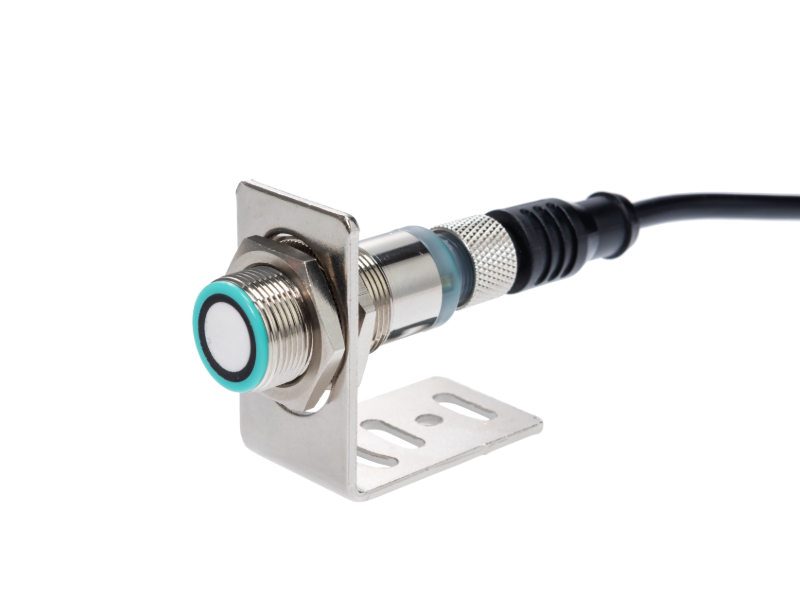
ISSRSensor 500mm Sensor ultrasónico de distancia de corto alcance y alta precisión|200kHz
-
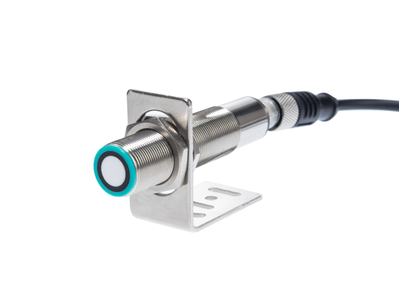
ISSRSensor Sensor ultrasónico todo en uno: Nivel de Alcance de 1m y Detección de Objetos
-
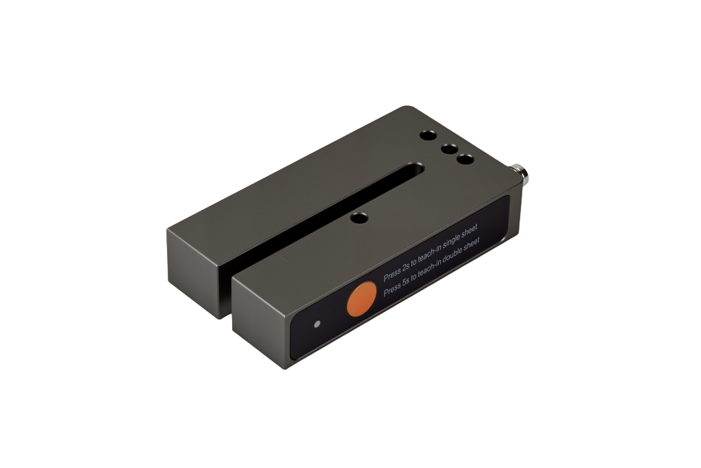
ISSRSensor: sensor ultrasónico de alta precisión para etiquetas en materiales transparentes y opacos
-
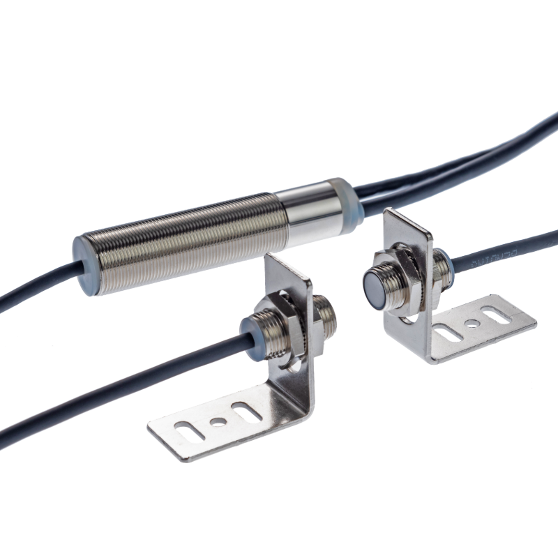
ISSRSensor M12 Sensor ultrasónico de detección de doble hoja
-
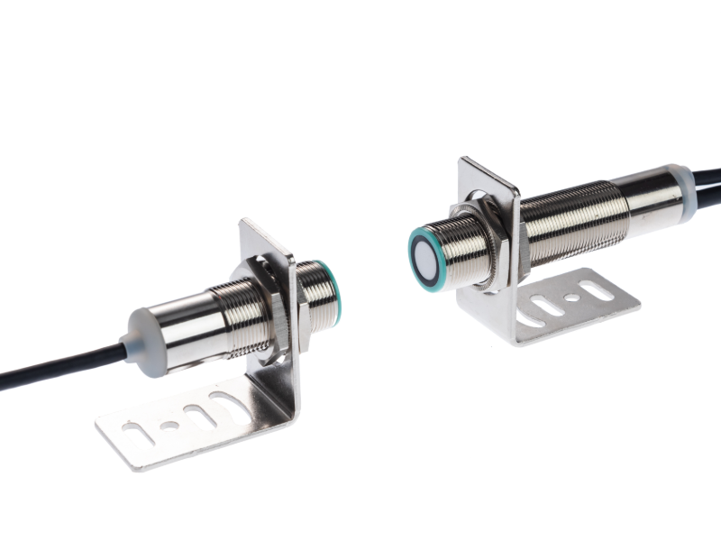
ISSRSensor Sensor ultrasónico de doble hoja | Detección multimaterial para automatización
-
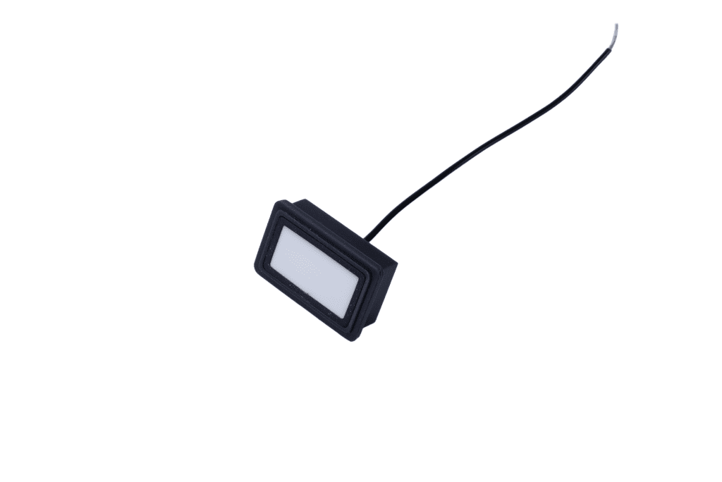
ISSRSensor Sensor ultrasónico de guiado de banda Transductor 160kHz - Sonda rectangular de detección y corrección de bordes
-

Sensor ultrasónico ISSRSensor F7J de la serie Economy