


Transparent films, dark rubber, and glossy liquid surfaces can cause transmission loss, weak reflection, or specular deflection in some optical measurement solutions. Ultrasonic sensing does not depend on target color or transparency, making it worth evaluating in these conditions—though it remains subject to surface angle, target size, and air conditions.
Once connected to a PLC, erratic readings do not necessarily indicate a probe fault. Blind zone, bracket reflections, input range configuration, reference potential, and VFD interference can all produce similar symptoms. During commissioning, first distinguish between sensor output, PLC raw values, and engineering-unit conversion, then troubleshoot each segment individually.
1. 200 kHz Ranging: Frequency, Compensation, and Measurement Limits
أن جهاز استشعار بالموجات فوق الصوتية emits a pulse and calculates distance from the round-trip time of flight. The speed of sound in air at 20 °C is approximately 343 m/s; at 200 kHz the wavelength is approximately 1.7 mm.
This frequency suits many short- to mid-range industrial measurements, but frequency alone does not determine resolution or blind zone. Transducer construction, transmit pulse, receive circuitry, and processing algorithms are equally important. A stated resolution figure does not equal absolute measurement accuracy.
What TVG and AGC Can Do
Some sensors employ Time-Varying Gain (TVG), which increases amplification as receive time progresses to capture weaker echoes from distant targets; Automatic Gain Control (AGC) adjusts gain based on echo amplitude.
Both help extend the receive dynamic range, but neither can recover a signal that has already been severely attenuated, nor can they guarantee reliable measurement in dense dust, steam, or thick foam. Whether a specific product incorporates these functions should be confirmed against its technical documentation.
Limits of Temperature Compensation
Near room temperature, a 10 °C change in air temperature shifts the speed of sound by approximately 1.8 %. If a fixed speed-of-sound value is still used for conversion, a 1 m distance can incur roughly 18 mm of error.
Built-in temperature compensation reduces this drift but cannot fully compensate for temperature gradients along the entire sound path. When the probe is mounted near an oven outlet, a cooling air knife, or a localized heat source, repositioning the sensor should take priority before verifying residual error.
Ultrasonic vs. Optical: Which to Choose
| التطبيق | Selection Guidance |
|---|---|
| Transparent film, dark rubber | Ultrasonic is often a good starting point, but actual echo must be verified |
| Smooth angled surfaces, small curved bottles | Ultrasonic may lose echoes; test angle and target size |
| Tiny parts, high-speed profile measurement | Small-spot, fast-response optical solutions are usually better suited |
| Thick foam, porous sound-absorbing materials | Ultrasonic may lose echoes or measure the foam surface instead |
| Dust, mist, condensation | Both technologies require verification; principle alone cannot guarantee reliability |
2. 4–20 mA vs. 0–10 V: Select by Loop Conditions
| Selection Factor | 4-20 مللي أمبير | 0–10 V |
|---|---|---|
| Long cable runs, high motor interference | Generally easier to achieve stable feedback | More sensitive to reference potential and routing |
| Direct connection to voltage-type AI input | Requires current channel or converter | Usually more straightforward |
| Line resistance effect | Typically minor when output voltage headroom is sufficient | Signal-wire voltage drop is small at high input impedance, but common-return voltage drop may cause offset |
| Fault diagnosis | Live zero helps identify signals below the valid range | 0 V can be confused with a valid zero |
| Key parameters to verify | Maximum output load, input type, isolation method | Input impedance, common reference, output drive capability |
4–20 mA is not a guarantee against interference. Wiring errors, overload conditions, supply disturbances, or common-mode voltage violations can still cause faults.
0–10 V does not have a universal “10-meter maximum” rule. Feasibility depends on cable type, routing, receiver configuration, and on-site testing. In high-interference environments, consider mounting distributed I/O close to the sensor to shorten signal lines.
3. Matching ISUB1000 and ISUB500 to Your Application
Start by verifying the nearest target distance, then check maximum range, physical envelope, and PLC interface. Different output variants within the same series are not interchangeable based on series name alone.
| المعلمة | ISUB1000-18GM76 Series | ISUB500-18GM45 Series |
|---|---|---|
| Stated sensing range | 70–1,000 mm | 30–500 mm |
| Physical blind zone | 70 mm | 30 mm |
| Operating frequency | 200 kHz | 200 كيلوهرتز تقريباً |
| القرار | Refer to full specification | 0.85 mm per product page |
| المخرجات | Selectable 4–20 mA or 0–10 V, plus Push-Pull switching | Analog, switching, or combined output per order configuration |
| التزامن | Supported per product page | Confirm per specific variant |
| Configuration method | Onboard buttons | Confirm teach-in procedure per variant |
The ISUB1000 suits stations requiring a wider measurement span, continuous feedback, and a simple presence/position signal. The ISUB500 is better suited to close-range, compact installations—but a 30 mm blind zone does not mean the target may touch the sensor face.
Analog and switching outputs share the same measurement chain and must not be treated as independent safety redundancy. Standard Push-Pull outputs cannot replace safety-rated emergency-stop or personnel-protection circuits.
4. Installation, Wiring, and PLC Calibration
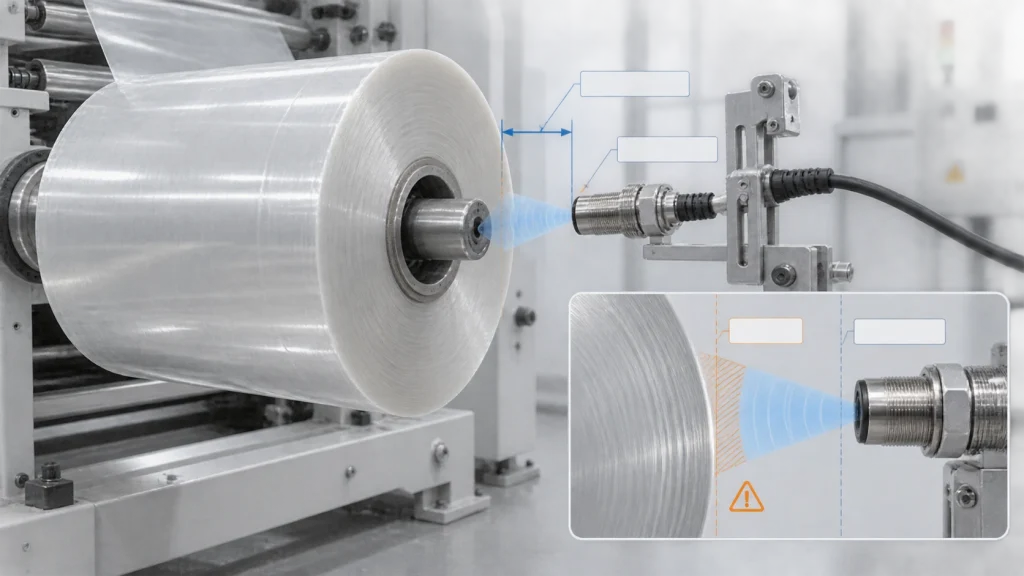
4.1 Verify the Acoustic Path First
- Stay clear of the blind zone: The nearest target distance must exceed the blind zone, with margin for vibration, assembly tolerances, and material variation. “Blind zone + 10 mm” is only a preliminary design reference.
- Allow beam clearance: Brackets, slot walls, pipe openings, and agitator components can generate false echoes. Use the manufacturer’s detection curves as reference; do not treat the −3 dB beam angle as a hard boundary.
- Aim at the target: Smooth targets should be measured as close to perpendicular as possible. Acceptable tilt angle depends on distance, surface, and probe type—do not assume a universal ±3° rule.
- Check for obstructions: Ribs, steps, and forward protrusions can create acoustic shadows. If necessary, translate the probe and retest.
- Use guide tubes with caution: A smooth inner wall or a tube diameter larger than the estimated beam cone does not guarantee freedom from parasitic echoes; verify tube length, diameter, and mounting position.
When a target enters the blind zone, the output may hold, jump, or enter a fault state—the specific behavior depends on model and configuration. Do not assume it will always be 20 mA or 10 V.
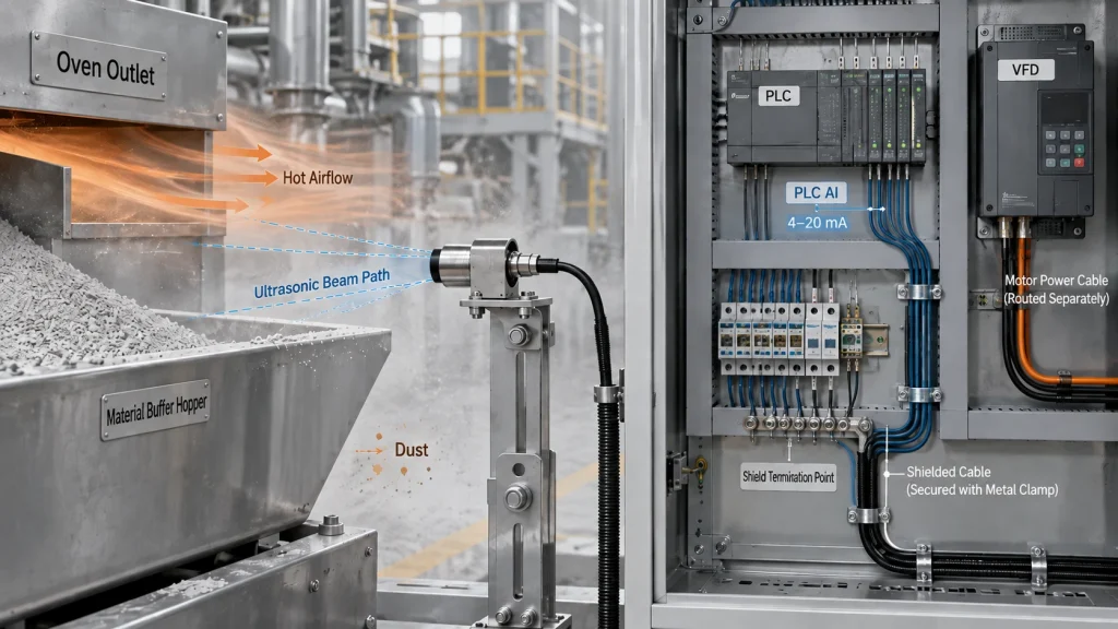
4.2 Confirm Input Type Before Wiring
Do not wire an M12 connector by wire color alone. Brown and blue are commonly used for supply, but white, black, and gray functions vary by model. Before powering up, verify the full order code, pinout diagram, and connector viewing direction.
Key checks when connecting to a PLC:
- Range matching: A 4–20 mA output must match the corresponding input configuration; same for 0–10 V.
- Active vs. passive interface: A three-wire sensor that actively sources current must connect to a compatible current input—never to an incompatible loop-powered terminal.
- Reference and return path: Non-isolated inputs require a correct common reference; isolated inputs follow the manual. Do not unconditionally short all AI−, MANA, and 0 V terminals together.
- Shielding and routing: Route signal cables away from motor and VFD power lines; when crossing is unavoidable, cross at approximately 90°. Whether the shield is grounded at one end or both ends should follow the sensor, PLC, and site EMC requirements.
4.3 Keep a Single Linear Conversion Formula
The general linear conversion is:
(Note: X can be a current value or a PLC raw count value, provided the input limits use the same unit.)
Example: measurement window set to 100–900 mm, mapped to 4–20 mA:
| Input Current | المسافة |
|---|---|
| 4 mA | 100 mm |
| 12 mA | 500 mm |
| 20 mA | 900 mm |
If a Siemens module is configured for 4–20 mA and its manual states the rated range corresponds to 0–27648, this count range can be used for normalization and scaling. Do not apply this range to all modules or all measurement ranges.
Studio 5000 projects should use CPT, applicable SCL instructions, or verified scaling AOIs based on the module’s data format. Do not assume all controllers share the same SCP instruction.
A reversed output lets current increase with level or roll diameter, but the percentage definition must still be confirmed. Level percentage does not necessarily equal volume percentage, and roll diameter percentage does not equal remaining material length percentage.
4.4 Verify with Three Points, Not a Single Reading
After calibration, record reference distance, sensor output, PLC raw value, and engineering-unit value at near-end, midpoint, and far-end. Repeat the test.
Then verify under motor start/stop, target tilt, multi-probe operation, and sensor power-cycle conditions. Anomalous signals should be diagnosed before being used for control; do not simply clamp or filter a fault into a “normal-looking” number.
4.5 Multi-Probe Crosstalk: Confirm Synchronization First
Enable probes one at a time and observe whether erratic readings appear when an adjacent probe is activated, then inspect the sound path and reflective surfaces.
Hardware synchronization can improve stability in some layouts but cannot guarantee crosstalk-free operation in all conditions. Time-division triggering reduces overlapping transmissions but lowers the refresh rate and requires sufficient echo-wait time.
Whether Sync pins can be paralleled, the permissible logic levels, trigger timing, and maximum connection count must be confirmed against the manufacturer’s documentation. Do not short Sync pins together simply because they share the same name, and do not connect them directly to a PLC 24 V digital output without verification.
5. Technical Limitations and Maintenance Requirements
Response speed: At 1 m, the acoustic round-trip time is approximately 5.83 ms; actual response also includes receive processing and filtering. For high-speed detection, verify the specific model’s response time, target dwell time, and PLC scan cycle. Resolution: 0.85 mm resolution does not mean ±0.85 mm accuracy, nor does it mean the sensor can resolve micrometer-level roll diameter changes. Precision positioning requires a measurement solution that meets the error budget. Foam and airflow: Thick foam may absorb echoes or cause the probe to measure the foam surface. Hot air, steam, and steep temperature gradients affect the sound path; software compensation cannot replace physical repositioning. Thermal stabilization and teach-in: ISUB500 public documentation recommends approximately 30 minutes of thermal stabilization before final accuracy checks, and notes that the analog variant’s teach-in window is limited to the first 5 minutes after power-up. The documentation also flags discrepancies in teach-in pulse descriptions; confirm the manufacturer-approved procedure before commissioning. Thermal stabilization verification and teach-in operations should be scheduled separately. Sensor face maintenance: IP67 does not imply resistance to condensation, all cleaning agents, or prolonged immersion. Periodically inspect for water droplets, frost, and deposits; use only manufacturer-approved cleaning methods and avoid hard-object scraping or unverified solvents.
Calibration intervals should be defined by operating conditions and accuracy requirements. If drift is detected, first investigate mounting, environment, and contamination—do not simply adjust PLC gain to mask the problem.
6. FAQ
Q1: PLC reading reaches 27648—is the sensor broken?
A1: Not necessarily. In common Siemens analog representations, 27648 is the rated full-scale count. First check input configuration, module diagnostics, and actual signal before concluding a fault.
Q2: Readings become erratic as the target gets closer—what to check first?
A2: First confirm whether the nearest distance has entered the blind zone, then check tilt angle, bracket echoes, and output slope. Post-echo-loss output behavior should be verified against the specific model’s manual.
Q3: I only have 0–10 V inputs—can I connect a 4–20 mA sensor?
A3: A resistor conversion or signal conditioner can be evaluated, but compatibility cannot be assumed. A 500 Ω resistor theoretically converts 4–20 mA to 2–10 V; verify output load capability, PLC input resistance, resistor power rating, and over-range headroom.
Q4: Does 4–20 mA below 3.6 mA always mean a broken wire?
A4: No. That threshold applies only to devices and configurations that adopt the corresponding fault convention. Low current may also result from power loss or sensor fault; combine module and sensor status for diagnosis.
Q5: Multiple probes show erratic readings simultaneously—will adding more filter help?
A5: Filtering smooths data but cannot eliminate false echoes. Verify crosstalk first, then apply synchronization, time-division triggering, or repositioning per the manufacturer’s guidance.
Q6: Teach-in fails after warm-up—what should I do?
A6: Check the teach-in window for your specific model. For variants that explicitly limit teach-in to the first 5 minutes after power-up, follow the approved procedure and re-power the sensor; do not experiment by connecting to positive or ground without authorization.
7. Engineering Summary and Resource Links
Acceptance testing for an ultrasonic sensor connected to a PLC should cover the full chain: Is the target measurable? Is the sound path reliable? Do output and input match? Can anomalous signals be identified?
Correct installation and wiring reduce false trips and maintenance troubleshooting time, but do not on that basis claim a specific MTBF improvement. MTBF requires a defined failure mode and operational records; process variation, measurement error, and hardware faults should be tracked separately.
Product scope and configuration can be verified via:
For wiring confirmation, non-standard windows, or custom interfaces, please provide target material, nearest and farthest distances, installation photos, cable length, and PLC input module model so our engineering team can verify compatibility.
Recommended Products
-
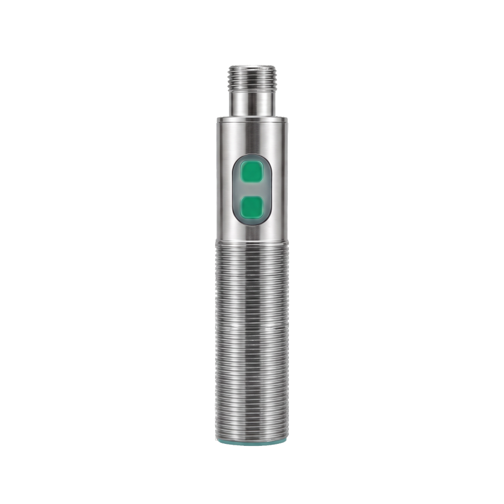
مستشعر الموجات فوق الصوتية ISSR 200 كيلوهرتز، طول 1 متر | 4-20 مللي أمبير/0-10 فولت، مزود بخاصية المزامنة، معيار IP67
-

جهاز استشعار المسافة بالموجات فوق الصوتية قصيرة المدى بالموجات فوق الصوتية قصيرة المدى بدقة فائقة تبلغ 0.15 م 400 كيلو هرتز
-

جهاز استشعار المسافة بالموجات فوق الصوتية المدمج بالكامل بالموجات فوق الصوتية ISSRSensor 1M 200 كيلو هرتز بزاوية قائمة 90 درجة منحنية بزاوية 90 درجة
-

جهاز استشعار المسافة بالموجات فوق الصوتية ISSRSensor 1M 200 كيلو هرتز مربع قابل للتعديل في اتجاه الكشف بالموجات فوق الصوتية مع وظيفة التزامن
-

مستشعر المستوى بالموجات فوق الصوتية الكل في واحد ISSRSensor 3M الكل في واحد | تناظري/التبديل/رقمي
-

جهاز استشعار المسافة بالموجات فوق الصوتية ISSRSensor 4M الكل في واحد مستشعر المسافة بالموجات فوق الصوتية/مخرج تناظري/رقمي
-

مستشعر المستوى بالموجات فوق الصوتية ISSRSensor 6M بالموجات فوق الصوتية |مستشعر مستوى الموجات فوق الصوتية متعدد المخرجات التناظرية/التبديل/ الرقمية
-

جهاز استشعار المسافة بالموجات فوق الصوتية قصيرة المدى عالية الدقة | 500 مم مستشعر مسافة قصيرة المدى بالموجات فوق الصوتية | 200 كيلو هرتز
-

مستشعر بالموجات فوق الصوتية قصير المدى | 30-500 مم | ISSR OEM/ODM