

1. 引言:为什么会出现“反转”现象?反转并非传感器故障——而是约定俗成的标准出现偏差
NPN vs PNP sensors differ in how their outputs switch current, while NO vs NC defines when the output turns on. For typical 24 VDC PLC inputs, PNP sensors connect to sinking inputs and NPN sensors connect to sourcing inputs. If a signal appears reversed, first verify electrical compatibility, then check switching mode and PLC program logic.

这种“反转”通常并非源于传感器检测故障,而是源于输出逻辑定义与PLC输入逻辑定义之间的不匹配。离散输出至少包含两层含义:
• NPN/PNP:这是两种不同的输出模式(输出极性/驱动模式)。它们决定了PLC数字输入(DI)端子最终呈现何种导通状态和电平逻辑。.
• NO/NC: These are normally open / normally closed contact logic rules. They determine how the sensor switches current and which PLC input circuit it can work with. The PLC input bit also depends on the input module and wiring.
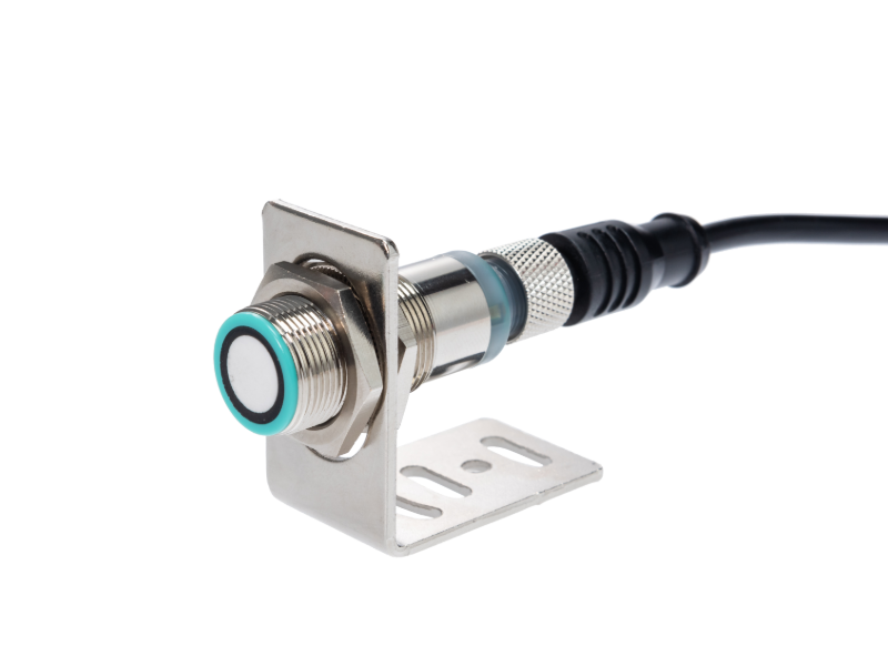
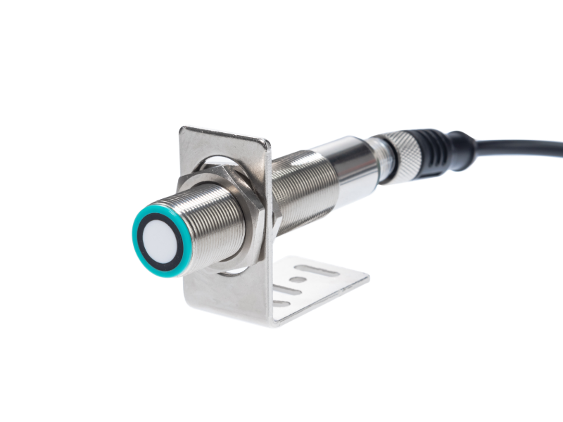
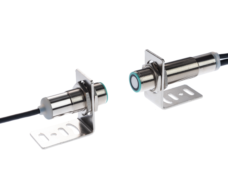
对于超声波传感器(例如, ISUB100系列),检测功能本身可能运行正常;但是,如果PLC侧的读数约定被反转,就会产生一种看似反相的故障。.
其核心工程方法是: 将输出逻辑设置为可验证的映射关系——确认NPN/PNP、NO/NC,并将其与PLC数字输入(DI)的公共端子类型相匹配。.
2. 首先,要明确区分两点:NPN/PNP决定的是什么,以及NO/NC决定的是什么
将离散传感器集成到PLC的数字输入(DI)时,请务必将“输出定义”分解为两层,并分别加以理解:
• NPN/PNP 解决了电气侧如何将信号发送至 PLC 的问题。.
• NO/NC 指明了在未触发与触发状态下,输出在逻辑侧呈现何种触点状态。.
An incompatible NPN/PNP output and PLC input is an electrical compatibility issue and may prevent the input from operating correctly. Separately, the NO/NC behavior or PLC program logic may be opposite to the intended application logic.

2.1 NPN/PNP:确定“输出与PLC数字输入公共端如何配合工作”
NPN/PNP 是两种不同的输出模式(输出极性/驱动模式)。 它们决定了在运行过程中,传感器输出电流(或导通路径)与PLC输入公共端之间的关系——从而影响PLC数字输入(DI)端所检测到的最终状态(在工程中通常表示为与公共端类型相对应的有效/无效电平)。 因此,要判断是否会发生反相,第一步并不是检查输出指示灯是否亮起。 相反,应将传感器输出类型与 PLC DI 端子的公共端子机制相匹配。在集成过程中,必须根据 PLC 数字输入配置确认应将输出设置为 NPN 还是 PNP,以确保输出信号与输入公共端子/有效电平兼容。.

2.2 NO/NC:确定“未触发/已触发”状态下的触点逻辑
NO/NC 表示常开/常闭(标准触点逻辑)。它定义了输出端子在两种状态下——未触发(物体不存在/未到位)和已触发(物体存在/到位)——应呈现的连接关系,从而影响 PLC 端的“有效定义”。”
一种直观的理解方式是:
• NO(常开):未触发时,通常处于断开状态;触发后,则转为接通状态。.
• NC(常闭):未触发时,通常处于有效连接/闭合状态;触发后,则转为无效连接/开启状态。.
需要注意的是,NO/NC 决定了逻辑方向(即触发时应变为“有效”还是“无效”)。它不会自动纠正 NPN/PNP 与公共端子之间的不匹配;这两者必须相互匹配。.
避免极性反转的关键:这不仅仅在于选择正确的NPN/PNP或NO/NC。 相反,必须将NPN/PNP(电气极性/与公共端子的配对方式)与NO/NC(触发逻辑方向)相匹配,并使其与PLC数字输入(DI)的公共端子类型及有效电平定义保持一致。.
3. 使用“逻辑映射表”来建立关系
为避免出现“接线正确但逻辑反转”的情况,最有效的工程方法是将传感器输出定义(NPN/PNP + NO/NC)与PLC数字输入(DI)的公共端子类型(公共正极/公共负极)转换为相同的判断规则——即:当目标处于位置/被触发时,以及当目标未处于位置/未被触发时,程序中应将PLC数字输入(DI)读取为高电平(有效 = 1)或低电平(无效 = 0)。.

The table above is based on a common operating mode for 24V discrete DI: when the sensor output matches the PLC DI common terminal type, the sensor output being conducting corresponds to the DI being valid. A mismatch between the sensor output type and the PLC input circuit is an electrical compatibility issue, not a reliable way to invert logic. Verify the current path and the module wiring requirements before evaluating NO/NC behavior.Different PLC input modules may differ slightly in their display method / valid definition, but the selection basis for the mapping relationship still follows the same logic. Ultimately, please confirm using the “field validation” in Section 5.
3.1 如何利用本表确定“反转”的原因”
• 首先,确认PLC的数字输入(DI)属于情况A还是情况B:检查COM是否连接到公共正极(+24V)或公共负极(0V)。.
• 然后确定传感器输出组合:NPN/PNP + NO/NC。.
• 匹配表中指定的、应在该位置读取或触发的输入值(1 或 0)。如果这与字段的行为不一致,通常意味着至少有一个定义不一致——最常见的情况是:
o an incompatible NPN/PNP output and PLC input, which may prevent correct electrical operation;
o the NO/NC switching behavior or the PLC program logic is opposite to the intended application logic.
4. PLC 接线与输入公共端子:通常发生反相的位置
“反转”并非由单一独立参数引起; 它通常发生在信号定义相互转换的阶段:当PLC端输入公共端子约定与传感器端输出有效电流流向/极性约定不一致时,或者当触点(常开/常闭)的选择与“触发=有效”的定义相反时。 特别是在将3/4线制传感器连接到PLC数字输入(DI)时,输入公共端(COM)的类型是决定该点是否会自然反相的关键因素。.
此外,以下工程变更也常会导致反相现象出现或被“触发”,例如: 更换PLC输入模块(不同模块的有效定义/显示方式各不相同)、更换隔离式/扩展式I/O,或者在维护过程中,仅更改接线却未同步确认传感器类型(NPN/PNP、常开/常闭)与PLC数字输入(DI)公共端子设置是否保持一致。.
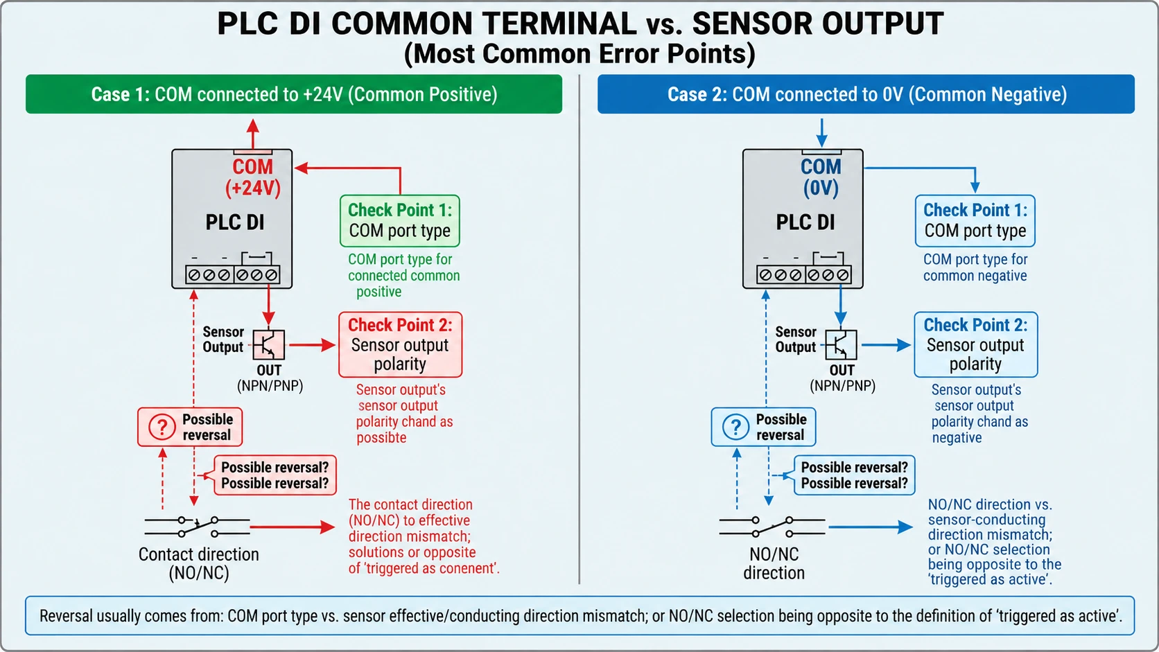
反相判断的主要依据:PLC数字输入(DI)的公共端类型 • 公共正极(COM连接至+24V):当外部负载电路以“有效=导通”的方式建立时,PLC数字输入通常会将其识别为高电平有效(1)。 • 共负(COM 连接至 0V):当外部电路建立时,PLC 数字输入端口的“有效”映射将根据公共端子端口的约定而变化,最终在程序端显示为读取高电平或低电平的哪一侧。.
5. 验证与故障排除工作流
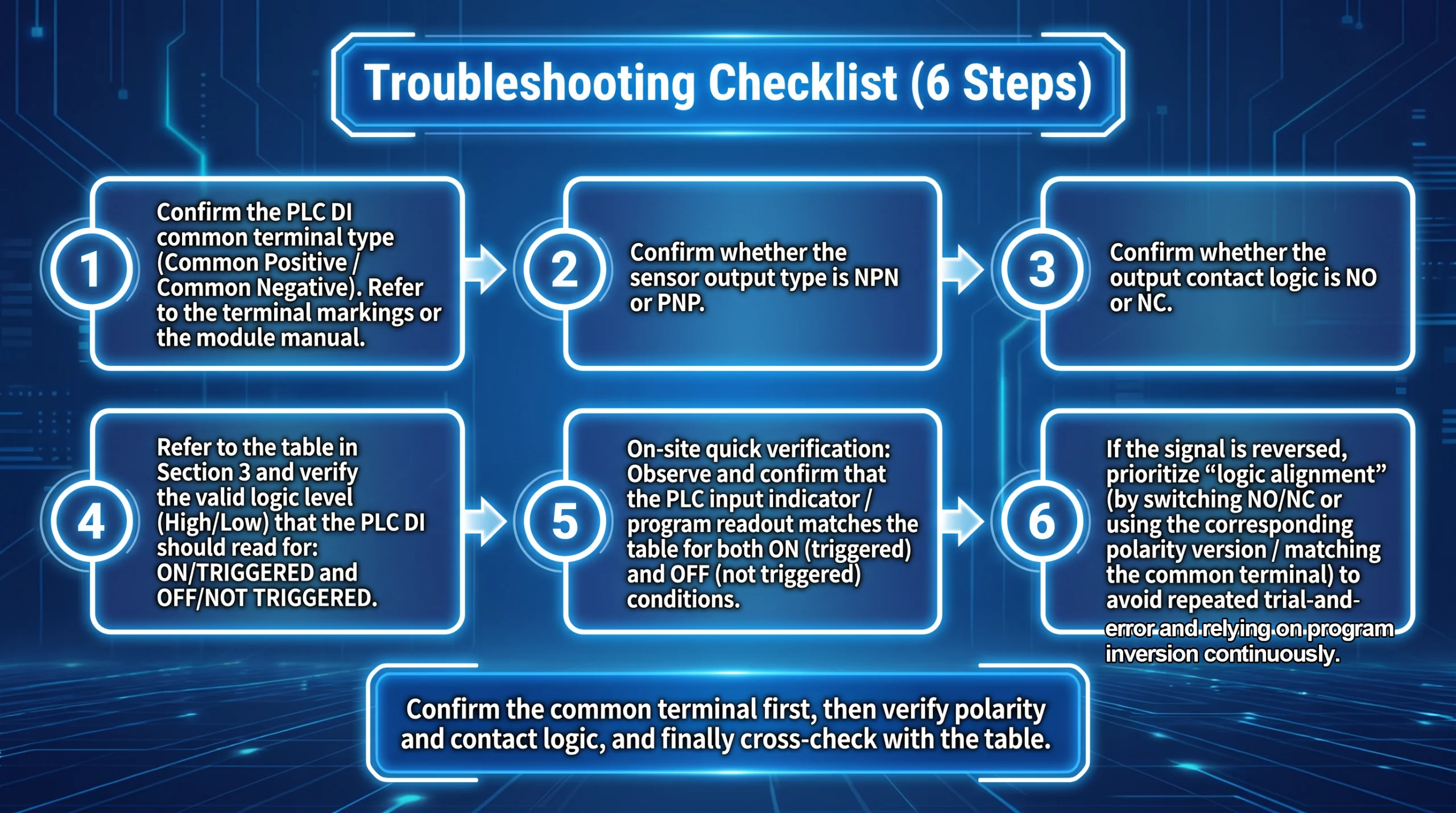
建议将故障排除转化为可重复使用的步骤清单,以减少反复试错的布线工作: 1.确认PLC数字输入(DI)公共端子类型(公共正极/公共负极)。请参照端子标识或模块手册。 2.确认传感器输出类型是NPN还是PNP。 3. 确认输出触点逻辑为常开(NO)还是常闭(NC)。 4. 参考第 3 节中的映射表,核实在“已进入/已触发”和“未进入/未触发”状态下,PLC 数字输入(DI)应读取的有效电平(高/低)。 5.现场快速验证:观察在“处于位置”和“未处于位置”两种状态下,PLC输入指示灯/程序读取值是否与表格一致。 6.若发现逻辑反转,应首先调整“逻辑对齐”(通过切换常开/常闭,或更换对应的极性版本/公共端子匹配),以避免反复试接线以及持续依赖PLC程序中的逻辑反转处理。.
6. 结论:避免倒装的最简规则
To reduce wiring and logic errors, verify three things separately: NPN/PNP electrical compatibility, NO/NC switching behavior, and the PLC application logic. Confirm the expected raw input bit in both triggered and not-triggered conditions, and document any intentional program inversion.
常见问题
问题1:我已经正确接线了,但显示仍然是反的。最有可能没有对齐的部件是什么?
A1: First verify electrical compatibility and wiring using the sensor and PLC module manuals. Then check the sensor’s NO/NC behavior and compare the raw PLC input bit and program logic with the intended application state.
问题2:移动到另一个工位时,同一位置会发生翻转——为什么?
A2: Check whether the two stations use different PLC input modules, COM wiring, sensor output versions, NO/NC settings, or PLC program logic. Verify electrical compatibility first, then compare the raw input bit and the application logic at both stations.
问题3:经过SET学习/调试后,反转现象变得更加明显。这种情况合理吗?
A3: Teaching or adjustment can change the switching point or detection window. If the signal changes repeatedly near a boundary, check the taught settings, hysteresis, target stability, and response time. This is different from a consistently inverted application signal. Teaching normally does not change the sensor’s NPN/PNP electrical output type.
问题4:如果信号明显反相,我能否直接在PLC程序中将其反相?
A4: Yes. If the sensor and PLC input are electrically compatible and the raw input is stable, program inversion can be a valid long-term design choice. Document the inversion and use clear variable names for both the raw input and the application state. Program inversion cannot fix an incompatible electrical connection and should not be treated as a safety measure.
问题 5:如何在现场快速确认是高电平有效还是低电平有效?
A5: Observe the raw PLC input bit in both triggered and not-triggered conditions, and compare it with the sensor output state and module documentation. If voltage polarity matters, measure the output voltage relative to the correct reference point. A PLC bit of 1 or 0 alone does not necessarily establish whether the sensor output voltage is active-high or active-low.
问题6:如果这是与联锁/安全相关的点(需要具有失效安全特性),应如何选择常开(NO)或常闭(NC)?
A6: Define the required safe state through a risk assessment and select appropriately rated sensors, input devices, diagnostics, and control architecture. An NC output alone does not make a sensing function fail-safe. Follow the applicable safety requirements and the device manufacturers’ instructions.